

SEARCH WHAT YOU WANT
How Distribution-Loop Design Protects RO+EDI Water Quality
Time:2026-10-21
An RO+EDI system can produce water that meets the required specification at the equipment outlet, yet the same water may fail to meet requirements at the production line.
The difference may develop after treatment: inside the storage tank, distribution piping, valves or connections to process equipment.
A distribution loop protects water quality by limiting contamination, maintaining controlled circulation and allowing effective cleaning, sanitization and monitoring. Its design should begin with the quality required at the point of use—not only the resistivity measured at the EDI outlet.
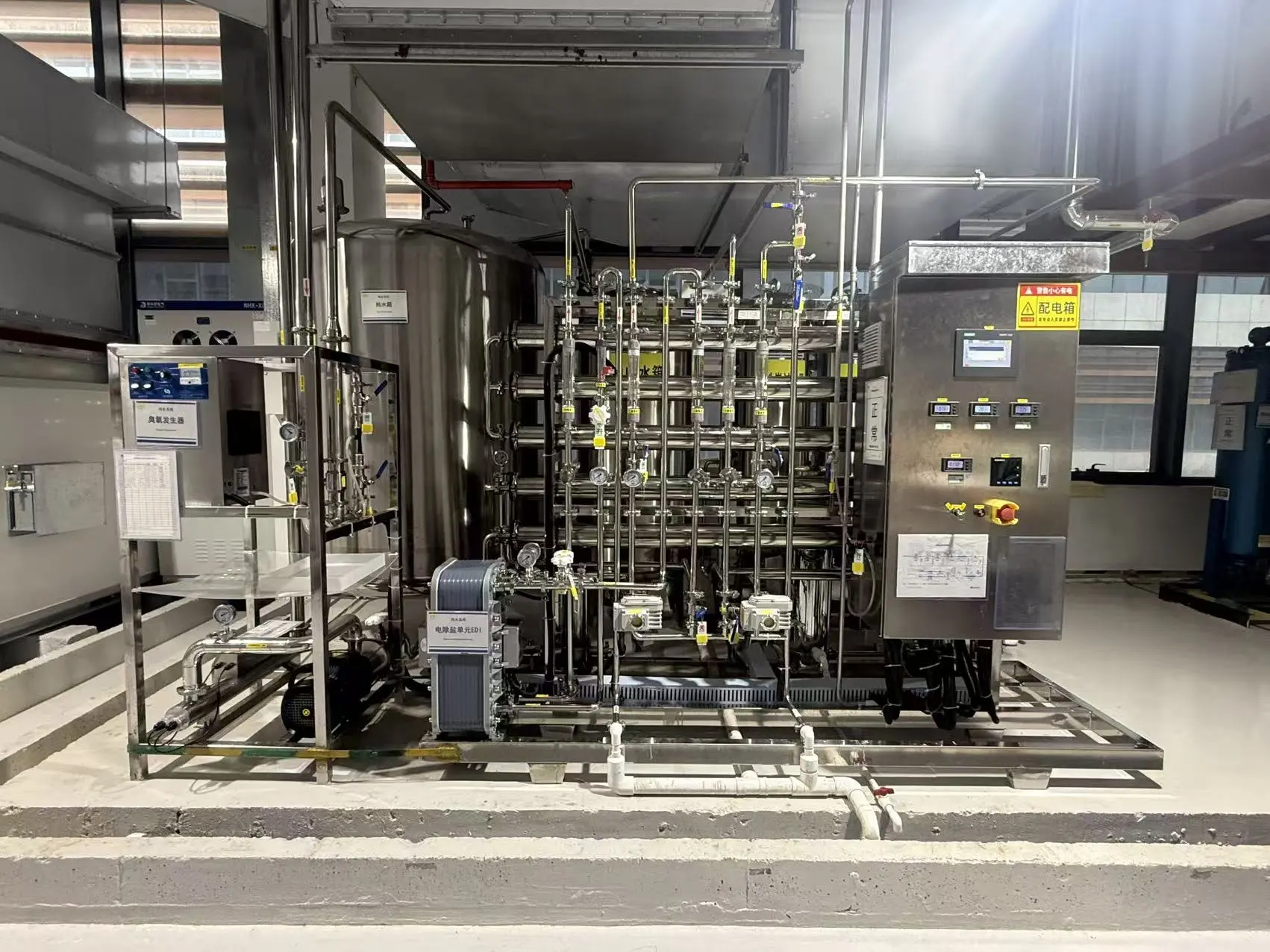
This article explains how storage and distribution affect RO+EDI water and what buyers should confirm before ordering a complete system.
1. Define Water Quality at the Point of Use
RO removes a large proportion of dissolved contaminants, while EDI provides further removal of residual ions and ionizable species. However, neither process guarantees that water will remain unchanged during storage and delivery. Veolia describes EDI as a process for removing residual salts and ionizable substances, including carbon dioxide and silica.
The distribution specification should therefore identify which characteristics matter to the application.
| Quality parameter | Why it matters in distribution |
|---|---|
| Conductivity or resistivity | Indicates changes in ionic contamination |
| Total organic carbon, where specified | Helps assess organic contamination |
| Microbial quality | Supports applications sensitive to microbial growth |
| Particles | Matters for sensitive rinsing and manufacturing processes |
| Specific contaminants | May include silica, boron or trace metals |
| Temperature | Affects process suitability, measurement interpretation and microbial-control strategy |
Not every project requires the same limits or instruments. Pharmaceutical manufacturing, electronics production and boiler makeup water have different quality priorities.
A high resistivity reading alone does not demonstrate compliance with microbial, organic or particle requirements.
The quotation should state whether water quality is guaranteed at the EDI outlet, loop supply, loop return or specified points of use. This follows the same measurement-boundary principle discussed in Rated Capacity vs Guaranteed Net Permeate: What RO Buyers Should Confirm.
2. Understand How Water Quality Changes After EDI
Distribution design should address the mechanisms that can introduce contamination.
Air contact
High-purity water can absorb carbon dioxide from air, increasing conductivity and reducing resistivity. Open tanks, poorly controlled vents and unsuitable sampling methods can expose water to atmospheric contamination.
Contact with system materials
Pipes, seals, valves, tank surfaces and pump components can introduce ions, organic substances or particles. Material grade, manufacturing cleanliness and installation quality all affect this risk.
Stagnation and microbial growth
Long residence times, infrequently used branches and poorly circulated sections can create conditions favorable to microbial growth and biofilm formation.
The FDA’s inspection guide for high-purity water systems highlights stagnant sections and distribution arrangements as concerns in pharmaceutical water systems. Although application-specific requirements differ, the underlying need to control stagnation is relevant to industrial high-purity water design.
Contamination from connected equipment
Process vessels, hoses and cleaning connections can introduce contamination if pressure reversals or unsuitable connections allow material to enter the water system.
A loop must therefore be assessed together with its tanks, branches and process interfaces.
3. Size the Storage Tank for Demand and Water Turnover
A storage tank buffers the difference between treatment-system output and production demand. Its usable volume should be based on the demand profile, replenishment rate and required reserve.
An unnecessarily large tank increases water residence time. An undersized tank may run short during peak consumption or cause excessive treatment-system cycling.
Before selecting tank volume, confirm:
-
• Average and maximum water demand.
-
• Duration of peak demand.
-
• RO+EDI replenishment capacity and operating hours.
-
• Minimum operating level and usable storage volume.
-
• Required reserve during planned interruptions.
-
• Expected turnover during weekends and low-production periods.
Recirculating tank water through a loop does not, by itself, replace that water with fresh production. Tank turnover and loop circulation are separate design considerations.
Protect the tank as part of the water system
The tank specification should address:
-
• A closed vessel with a suitable vent arrangement.
-
• Compatible internal surfaces and seals.
-
• Drainability and accessible inspection points.
-
• Return-water entry and adequate mixing.
-
• Level protection and overflow arrangements.
-
• Cleaning and sanitization coverage.
A microbial vent filter does not remove carbon dioxide from incoming air. Where atmospheric gas absorption could prevent compliance with the required resistivity, the design may need additional gas-control measures.
Any gas-blanketing arrangement must also account for gas quality, tank pressure and vacuum protection.
4. Maintain Circulation During Both Peak and Low Demand
A typical distribution arrangement supplies water from a tank through a circulation pump, serves multiple takeoff points and returns unused water to the tank or a designated polishing stage.
The return path allows circulation to continue when production demand falls. However, a loop on a drawing does not prove that every section receives adequate flow.
Check return flow at maximum consumption
For a simple loop without additional side streams:
Loop supply flow = Total point-of-use withdrawal + Loop return flow
For example, if simultaneous withdrawal is 4 m³/h and the design requires 2 m³/h to remain in the return:
Required loop supply flow = 4 + 2 = 6 m³/h
These values are illustrative. The required return flow must be determined from the actual piping and operating strategy.
The circulation pump must provide that flow at the necessary head, accounting for pipe friction, valves, treatment devices and required point-of-use pressure.
This circulation duty is different from the RO+EDI production rate. Returning water is reused within the loop; the treatment plant replenishes withdrawals and other losses.
Check minimum-demand operation
When little water is being used, the system should avoid excessive pressure, unnecessary heat buildup and inefficient operation.
A VFD can support pressure or flow control, but the control logic must also preserve the required return flow. The relationship between control strategy and pump operation is discussed in How VFD Control Improves RO Pump Efficiency and System Stability.
Evaluate velocity by section
There is no single circulation velocity that guarantees water quality for every application.
Pipe diameter and flow should be selected together, considering hydraulic losses, temperature, material limits and the contamination-control strategy. Flow decreases along the supply header as users withdraw water, so checking only pump discharge velocity is insufficient.
Circulation supports water-quality control, but it does not sterilize the loop or remove established biofilm.
5. Design Branches, Materials and Connections for Clean Operation
Minimize stagnant branches
A continuously circulating main header can still contain stagnant takeoff branches.
Review:
-
• Long connections between the header and use valves.
-
• Unused future connections.
-
• Instrument pockets and bypasses.
-
• Isolated filter housings.
-
• Hoses left connected between production runs.
Where practical, place takeoffs close to the circulating header and use suitable low-retention components. For infrequently used branches, define an appropriate flushing or local circulation strategy.
Avoid applying a universal dead-leg ratio without identifying the relevant project requirements, component geometry and sanitization method.
Select materials for the complete operating cycle
Material selection should consider normal service, cleaning chemicals and sanitization conditions.
| Component | Selection considerations |
|---|---|
| Piping and tank | Contaminant release, corrosion resistance, temperature and pressure |
| Valves | Internal retention, drainability and sanitization compatibility |
| Seals and gaskets | Extractables, chemical resistance and service temperature |
| Pump | Wetted materials, seal arrangement and cleanability |
| Instruments | Wetted surfaces, installation geometry and servicing requirements |
Properly specified stainless steel and high-purity polymers can both be appropriate, depending on the application. GF offers high-purity PVDF piping specifically for demanding microelectronics water systems, illustrating why purity-related material specifications extend beyond basic pressure ratings.
Specify joining methods, inspection and installation cleanliness as well as material names. A suitable pipe can still be compromised by poor joints, contaminated assembly or incompatible seals.
Protect process interfaces
Assess the possibility of backflow from connected equipment under normal operation, shutdown and cleaning.
The required protection should reflect the process hazard and hydraulic arrangement. Do not assume one generic check valve is sufficient for every connection.
6. Plan Sanitization and Polishing Before Selecting Components
The intended sanitization method affects the tank, piping, seals, instruments and treatment devices. It should be selected before the component list is finalized.
Possible approaches include thermal or chemical sanitization, with the method chosen for the application and materials involved.
Confirm:
-
• Which sections will be exposed to the treatment.
-
• How temperature or chemical concentration will be verified.
-
• How branches and normally isolated sections will be covered.
-
• Which components must be isolated.
-
• How sanitant residues will be removed.
-
• What checks are required before water returns to production.
Do not assume the EDI module can tolerate the loop’s sanitization conditions. Compatibility and isolation requirements must follow the selected equipment’s instructions.
Give each polishing device a defined purpose
UV treatment and final filters can support a distribution strategy, but they have different roles.
A UV unit does not sanitize downstream pipe surfaces. A final filter does not remove dissolved ions or correct upstream biofilm. UV systems for microbial control and those intended for TOC reduction also require different design considerations.
If ozone is used, its compatibility, monitoring and removal before sensitive points of use must be addressed.
Each device should solve an identified water-quality problem and be included in the maintenance and verification plan.
7. Monitor Where Water Quality Can Change
Monitoring only the EDI outlet can miss contamination introduced during storage and distribution.
A practical monitoring plan considers the treatment outlet, loop supply, loop return and representative points of use.
| Location | What it helps verify |
|---|---|
| EDI outlet | Performance of the treatment equipment |
| Loop supply | Water entering distribution after storage and any polishing |
| Loop return | Changes across the circulating system |
| Critical or remote points of use | Water quality delivered to the process |
Select instruments and sampling methods according to the required parameters. Conductivity or resistivity, temperature, flow and pressure may be monitored online; other requirements may need additional analyzers or laboratory testing.
For high-purity water, atmospheric exposure during sampling can alter conductivity. Measurement methods and temperature-compensation settings should therefore be defined.
The control system should also specify what happens when quality limits are exceeded or a critical sensor fails. Possible responses include an alarm, diversion or inhibition of supply to affected users.
These requirements should be coordinated with the approach described in Essential Online Instruments for Automatic Industrial RO Systems.
8. Verify Performance Under Real Operating Conditions
Acceptance testing should demonstrate that the complete system delivers the required water quality and pressure under the agreed operating scenarios.
A test with every point-of-use valve closed does not establish performance during peak demand. Likewise, a short test immediately after sanitization does not establish long-term microbial control.
The verification plan should address:
-
• Simultaneous peak withdrawals.
-
• Minimum-demand circulation.
-
• Return flow and critical outlet pressures.
-
• Tank operating levels and replenishment.
-
• Representative point-of-use water quality.
-
• Sanitization coverage and return-to-service checks.
-
• Restart after agreed periods of low use or shutdown.
-
• Alarm and protective-control functions.
Longer-term monitoring should be defined where the application requires evidence of sustained control.
What Buyers Should Confirm Before Ordering
Request a coordinated distribution package rather than separate quotations for a tank, pump and piping.
The supplier’s proposal should identify:
-
Water-quality limits and their measurement points.
-
Demand profile, tank usable volume and replenishment assumptions.
-
Loop layout, branch details and future connections.
-
Pump duty and minimum return-flow requirements.
-
Wetted materials, joining methods and inspection requirements.
-
Sanitization method and component compatibility.
-
Monitoring, sampling and off-specification responses.
-
Installation scope, commissioning tests and ongoing maintenance responsibilities.
The supply boundary should also be clear. A skid-only quotation may exclude the very tank and piping that determine final delivery quality. For a wider scope review, see How to Compare Industrial RO System Quotations: 12 Technical Points Buyers Should Check.
Plan RO+EDI Treatment and Distribution Together
The quality required by production must be maintained from the treatment outlet to the actual point of use. Storage, circulation, materials, sanitization and monitoring all contribute to that result.
Planning an RO+EDI project? Send Zhongnuo Water Treatment your raw-water analysis, required point-of-use water quality, hourly and daily demand, operating schedule and proposed equipment layout. These details help our engineering team coordinate treatment capacity with storage and distribution requirements.
An RO+EDI system can produce water that meets the required specification at the equipment outlet, yet the same water may fail to meet requirements at the production line.
The difference may develop after treatment: inside the storage tank, distribution piping, valves or connections to process equipment.
A distribution loop protects water quality by limiting contamination, maintaining controlled circulation and allowing effective cleaning, sanitization and monitoring. Its design should begin with the quality required at the point of use—not only the resistivity measured at the EDI outlet.
This article explains how storage and distribution affect RO+EDI water and what buyers should confirm before ordering a complete system.
1. Define Water Quality at the Point of Use
RO removes a large proportion of dissolved contaminants, while EDI provides further removal of residual ions and ionizable species. However, neither process guarantees that water will remain unchanged during storage and delivery. Veolia describes EDI as a process for removing residual salts and ionizable substances, including carbon dioxide and silica.
The distribution specification should therefore identify which characteristics matter to the application.
| Quality parameter | Why it matters in distribution |
|---|---|
| Conductivity or resistivity | Indicates changes in ionic contamination |
| Total organic carbon, where specified | Helps assess organic contamination |
| Microbial quality | Supports applications sensitive to microbial growth |
| Particles | Matters for sensitive rinsing and manufacturing processes |
| Specific contaminants | May include silica, boron or trace metals |
| Temperature | Affects process suitability, measurement interpretation and microbial-control strategy |
Not every project requires the same limits or instruments. Pharmaceutical manufacturing, electronics production and boiler makeup water have different quality priorities.
A high resistivity reading alone does not demonstrate compliance with microbial, organic or particle requirements.
The quotation should state whether water quality is guaranteed at the EDI outlet, loop supply, loop return or specified points of use. This follows the same measurement-boundary principle discussed in Rated Capacity vs Guaranteed Net Permeate: What RO Buyers Should Confirm.
2. Understand How Water Quality Changes After EDI
Distribution design should address the mechanisms that can introduce contamination.
Air contact
High-purity water can absorb carbon dioxide from air, increasing conductivity and reducing resistivity. Open tanks, poorly controlled vents and unsuitable sampling methods can expose water to atmospheric contamination.
Contact with system materials
Pipes, seals, valves, tank surfaces and pump components can introduce ions, organic substances or particles. Material grade, manufacturing cleanliness and installation quality all affect this risk.
Stagnation and microbial growth
Long residence times, infrequently used branches and poorly circulated sections can create conditions favorable to microbial growth and biofilm formation.
The FDA’s inspection guide for high-purity water systems highlights stagnant sections and distribution arrangements as concerns in pharmaceutical water systems. Although application-specific requirements differ, the underlying need to control stagnation is relevant to industrial high-purity water design.
Contamination from connected equipment
Process vessels, hoses and cleaning connections can introduce contamination if pressure reversals or unsuitable connections allow material to enter the water system.
A loop must therefore be assessed together with its tanks, branches and process interfaces.
3. Size the Storage Tank for Demand and Water Turnover
A storage tank buffers the difference between treatment-system output and production demand. Its usable volume should be based on the demand profile, replenishment rate and required reserve.
An unnecessarily large tank increases water residence time. An undersized tank may run short during peak consumption or cause excessive treatment-system cycling.
Before selecting tank volume, confirm:
-
• Average and maximum water demand.
-
• Duration of peak demand.
-
• RO+EDI replenishment capacity and operating hours.
-
• Minimum operating level and usable storage volume.
-
• Required reserve during planned interruptions.
-
• Expected turnover during weekends and low-production periods.
Recirculating tank water through a loop does not, by itself, replace that water with fresh production. Tank turnover and loop circulation are separate design considerations.
Protect the tank as part of the water system
The tank specification should address:
-
• A closed vessel with a suitable vent arrangement.
-
• Compatible internal surfaces and seals.
-
• Drainability and accessible inspection points.
-
• Return-water entry and adequate mixing.
-
• Level protection and overflow arrangements.
-
• Cleaning and sanitization coverage.
A microbial vent filter does not remove carbon dioxide from incoming air. Where atmospheric gas absorption could prevent compliance with the required resistivity, the design may need additional gas-control measures.
Any gas-blanketing arrangement must also account for gas quality, tank pressure and vacuum protection.
4. Maintain Circulation During Both Peak and Low Demand
A typical distribution arrangement supplies water from a tank through a circulation pump, serves multiple takeoff points and returns unused water to the tank or a designated polishing stage.
The return path allows circulation to continue when production demand falls. However, a loop on a drawing does not prove that every section receives adequate flow.
Check return flow at maximum consumption
For a simple loop without additional side streams:
Loop supply flow = Total point-of-use withdrawal + Loop return flow
For example, if simultaneous withdrawal is 4 m³/h and the design requires 2 m³/h to remain in the return:
Required loop supply flow = 4 + 2 = 6 m³/h
These values are illustrative. The required return flow must be determined from the actual piping and operating strategy.
The circulation pump must provide that flow at the necessary head, accounting for pipe friction, valves, treatment devices and required point-of-use pressure.
This circulation duty is different from the RO+EDI production rate. Returning water is reused within the loop; the treatment plant replenishes withdrawals and other losses.
Check minimum-demand operation
When little water is being used, the system should avoid excessive pressure, unnecessary heat buildup and inefficient operation.
A VFD can support pressure or flow control, but the control logic must also preserve the required return flow. The relationship between control strategy and pump operation is discussed in How VFD Control Improves RO Pump Efficiency and System Stability.
Evaluate velocity by section
There is no single circulation velocity that guarantees water quality for every application.
Pipe diameter and flow should be selected together, considering hydraulic losses, temperature, material limits and the contamination-control strategy. Flow decreases along the supply header as users withdraw water, so checking only pump discharge velocity is insufficient.
Circulation supports water-quality control, but it does not sterilize the loop or remove established biofilm.
5. Design Branches, Materials and Connections for Clean Operation
Minimize stagnant branches
A continuously circulating main header can still contain stagnant takeoff branches.
Review:
-
• Long connections between the header and use valves.
-
• Unused future connections.
-
• Instrument pockets and bypasses.
-
• Isolated filter housings.
-
• Hoses left connected between production runs.
Where practical, place takeoffs close to the circulating header and use suitable low-retention components. For infrequently used branches, define an appropriate flushing or local circulation strategy.
Avoid applying a universal dead-leg ratio without identifying the relevant project requirements, component geometry and sanitization method.
Select materials for the complete operating cycle
Material selection should consider normal service, cleaning chemicals and sanitization conditions.
| Component | Selection considerations |
|---|---|
| Piping and tank | Contaminant release, corrosion resistance, temperature and pressure |
| Valves | Internal retention, drainability and sanitization compatibility |
| Seals and gaskets | Extractables, chemical resistance and service temperature |
| Pump | Wetted materials, seal arrangement and cleanability |
| Instruments | Wetted surfaces, installation geometry and servicing requirements |
Properly specified stainless steel and high-purity polymers can both be appropriate, depending on the application. GF offers high-purity PVDF piping specifically for demanding microelectronics water systems, illustrating why purity-related material specifications extend beyond basic pressure ratings.
Specify joining methods, inspection and installation cleanliness as well as material names. A suitable pipe can still be compromised by poor joints, contaminated assembly or incompatible seals.
Protect process interfaces
Assess the possibility of backflow from connected equipment under normal operation, shutdown and cleaning.
The required protection should reflect the process hazard and hydraulic arrangement. Do not assume one generic check valve is sufficient for every connection.
6. Plan Sanitization and Polishing Before Selecting Components
The intended sanitization method affects the tank, piping, seals, instruments and treatment devices. It should be selected before the component list is finalized.
Possible approaches include thermal or chemical sanitization, with the method chosen for the application and materials involved.
Confirm:
-
• Which sections will be exposed to the treatment.
-
• How temperature or chemical concentration will be verified.
-
• How branches and normally isolated sections will be covered.
-
• Which components must be isolated.
-
• How sanitant residues will be removed.
-
• What checks are required before water returns to production.
Do not assume the EDI module can tolerate the loop’s sanitization conditions. Compatibility and isolation requirements must follow the selected equipment’s instructions.
Give each polishing device a defined purpose
UV treatment and final filters can support a distribution strategy, but they have different roles.
A UV unit does not sanitize downstream pipe surfaces. A final filter does not remove dissolved ions or correct upstream biofilm. UV systems for microbial control and those intended for TOC reduction also require different design considerations.
If ozone is used, its compatibility, monitoring and removal before sensitive points of use must be addressed.
Each device should solve an identified water-quality problem and be included in the maintenance and verification plan.
7. Monitor Where Water Quality Can Change
Monitoring only the EDI outlet can miss contamination introduced during storage and distribution.
A practical monitoring plan considers the treatment outlet, loop supply, loop return and representative points of use.
| Location | What it helps verify |
|---|---|
| EDI outlet | Performance of the treatment equipment |
| Loop supply | Water entering distribution after storage and any polishing |
| Loop return | Changes across the circulating system |
| Critical or remote points of use | Water quality delivered to the process |
Select instruments and sampling methods according to the required parameters. Conductivity or resistivity, temperature, flow and pressure may be monitored online; other requirements may need additional analyzers or laboratory testing.
For high-purity water, atmospheric exposure during sampling can alter conductivity. Measurement methods and temperature-compensation settings should therefore be defined.
The control system should also specify what happens when quality limits are exceeded or a critical sensor fails. Possible responses include an alarm, diversion or inhibition of supply to affected users.
These requirements should be coordinated with the approach described in Essential Online Instruments for Automatic Industrial RO Systems.
8. Verify Performance Under Real Operating Conditions
Acceptance testing should demonstrate that the complete system delivers the required water quality and pressure under the agreed operating scenarios.
A test with every point-of-use valve closed does not establish performance during peak demand. Likewise, a short test immediately after sanitization does not establish long-term microbial control.
The verification plan should address:
-
• Simultaneous peak withdrawals.
-
• Minimum-demand circulation.
-
• Return flow and critical outlet pressures.
-
• Tank operating levels and replenishment.
-
• Representative point-of-use water quality.
-
• Sanitization coverage and return-to-service checks.
-
• Restart after agreed periods of low use or shutdown.
-
• Alarm and protective-control functions.
Longer-term monitoring should be defined where the application requires evidence of sustained control.
What Buyers Should Confirm Before Ordering
Request a coordinated distribution package rather than separate quotations for a tank, pump and piping.
The supplier’s proposal should identify:
-
Water-quality limits and their measurement points.
-
Demand profile, tank usable volume and replenishment assumptions.
-
Loop layout, branch details and future connections.
-
Pump duty and minimum return-flow requirements.
-
Wetted materials, joining methods and inspection requirements.
-
Sanitization method and component compatibility.
-
Monitoring, sampling and off-specification responses.
-
Installation scope, commissioning tests and ongoing maintenance responsibilities.
The supply boundary should also be clear. A skid-only quotation may exclude the very tank and piping that determine final delivery quality. For a wider scope review, see How to Compare Industrial RO System Quotations: 12 Technical Points Buyers Should Check.
Plan RO+EDI Treatment and Distribution Together
The quality required by production must be maintained from the treatment outlet to the actual point of use. Storage, circulation, materials, sanitization and monitoring all contribute to that result.
Planning an RO+EDI project? Send Zhongnuo Water Treatment your raw-water analysis, required point-of-use water quality, hourly and daily demand, operating schedule and proposed equipment layout. These details help our engineering team coordinate treatment capacity with storage and distribution requirements.
Previous: No more data
Get a Quote for Free
Submit this form and our sales representative will contact you soon.


ONLINE MESSAGE
Copyright © 2026 Zhongnuo Water Treatment Co., Ltd.