

SEARCH WHAT YOU WANT
Essential Online Instruments for Automatic Industrial RO Systems
Time:2026-10-12
An automatic reverse osmosis system needs more than a PLC and touchscreen. It needs reliable measurements to confirm that feedwater is available, operating conditions remain within design limits and product water meets the required specification.
For most industrial RO systems, the core measurements are pressure, flow, conductivity, temperature and tank level. Additional instruments should address specific feedwater risks, chemical-dosing requirements and final water applications.
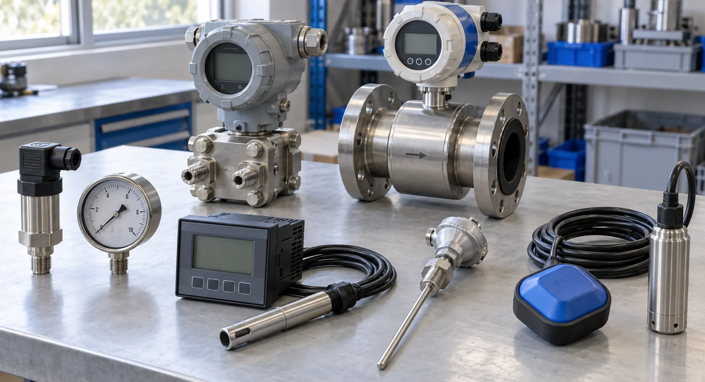
When comparing quotations, confirm three things for each instrument: what it measures, where it is installed and what action follows an abnormal reading.
1. Which Online Instruments Does an RO System Need?
The following table provides a practical starting point. The final configuration should reflect the process design, required automation and consequences of equipment failure.
| Measurement | Typical Location | Main Function |
|---|---|---|
| Pressure | High-pressure pump suction and discharge; membrane feed and concentrate lines | Monitor operating pressure and support equipment protection |
| Differential pressure | Across cartridge filters and membrane stages | Track increasing hydraulic resistance |
| Flow | Feedwater, permeate and concentrate lines | Verify output, calculate recovery and identify abnormal flow |
| Conductivity | RO feedwater and permeate outlets | Monitor salinity changes and product-water ionic quality |
| Temperature | RO feedwater line | Interpret performance changes and identify temperature excursions |
| Level | Raw-water, product-water and chemical tanks, where fitted | Support automatic filling, start/stop control and low-level protection |
A local pressure gauge or visual flow meter helps an operator inspect the system, but it does not necessarily send a signal to the PLC. Any measurement used for automatic control must have a suitable electrical or communication output.
2. Pressure and Flow: Confirm Safe Operating Conditions
Pressure and flow should be evaluated together. Pressure indicates the hydraulic conditions, while flow confirms how much water moves through the system.
Pressure and differential pressure
A typical instrumentation arrangement monitors:
-
• Pump suction pressure: identifies inadequate feed pressure and supports pump-protection interlocks.
-
• Pump discharge or membrane feed pressure: confirms operation within the specified pressure range.
-
• Cartridge-filter differential pressure: indicates increasing resistance through the filter.
-
• Membrane-stage differential pressure: helps identify changes in resistance through the membrane array.
Low suction pressure protection can reduce the risk of pump damage, but it should not be treated as proof that every dry-running condition will be detected. Tank level, feed availability and other protective functions must suit the installation.
Likewise, increasing differential pressure can indicate fouling or blockage, but does not identify the cause by itself. Compare readings at comparable flow conditions and investigate before deciding on maintenance.
For VFD-controlled pumps, specify whether speed is controlled by pressure, permeate flow or another process variable. The protective limits must remain effective throughout the operating range, as discussed in How VFD Control Improves RO Pump Efficiency and System Stability.
Flow and recovery
For a simple single-pass RO system without recycle or additional withdrawals:
Feedwater flow = Permeate flow + Concentrate flow
Recovery (%) = Permeate flow ÷ Feedwater flow × 100
For example, a system receiving 20 m³/h of feedwater and producing 15 m³/h of permeate operates at 75% recovery, with approximately 5 m³/h of concentrate.
Measuring all three streams provides a useful water-balance check. Measuring two and calculating the third may be acceptable for a simpler design, provided the measurement boundary is clear.
Permeate flow alone cannot confirm acceptable recovery or sufficient concentrate flow.
Systems with recycle, bypasses or multiple passes need measurement points that distinguish fresh feedwater from internal circulation. The control specification should also define the response to excessive recovery or insufficient concentrate flow.
3. Conductivity and Temperature: Verify Quality and Interpret Performance
Producing the specified flow is only useful if the water also meets the required quality.
Measure conductivity at the relevant product outlet
Online permeate conductivity supports continuous monitoring of ionic quality. When conductivity exceeds the agreed limit, the control system should trigger a defined response, such as an alarm, product-water diversion or shutdown.
The sensor and diversion valve must be positioned so that off-specification water can be kept out of the product tank. Startup logic should define when water is accepted into normal service.
For double-pass RO, first-pass conductivity does not establish final product quality. Systems with EDI or other polishing equipment may require additional measurement points.
The monitored location should match the delivery specification described in Rated Capacity vs Guaranteed Net Permeate: What RO Buyers Should Confirm.
Conductivity does not independently verify microbiological quality, organic contamination or every application-specific water requirement.
Use feed conductivity and temperature for context
Feedwater conductivity helps identify salinity changes. When feed and permeate measurements use a consistent temperature-compensation basis, they can support an approximate conductivity-based rejection calculation:
Apparent rejection (%) = [1 − (Permeate conductivity ÷ Feed conductivity)] × 100
This is a useful operating indicator, not a measurement of rejection for every individual dissolved substance.
Temperature also affects interpretation. Colder feedwater generally reduces permeate flow at otherwise comparable conditions, while changes in salinity or pressure can also alter output. These effects should be considered before concluding that membranes have deteriorated.
For projects with seasonal water-quality changes, see How Variable Feedwater TDS Affects RO Pump and Membrane Selection.
4. Level and Chemical Monitoring: Address Upstream Risks
Additional instruments should be selected according to the failures the system needs to detect.
| Instrument | When It Is Needed | Key Design Consideration |
|---|---|---|
| Tank-level switch or transmitter | Tank-fed systems and automatic storage management | Define low-level protection, stop levels and restart levels |
| Online pH analyzer | Automatic acid or alkali dosing; processes requiring pH limits | Measure after adequate mixing and account for response delay |
| ORP and/or residual chlorine analyzer | Feedwater with a relevant oxidation risk | Match the monitoring method to the water chemistry and membrane requirements |
| Online turbidity analyzer | Variable feedwater or pretreatment requiring continuous supervision | Use as an indicator of particulate changes, not a substitute for SDI testing |
| Dosing-flow monitor or pump fault signal | Applications where loss of chemical dosing could damage membranes | Verify dosing performance beyond chemical-tank level |
Match pH monitoring to the dosing function
Online pH is particularly relevant to automatic acid or alkali dosing. It is not a universal control method for antiscalant dosing.
Antiscalant dosage is normally established from water chemistry, recovery and the chemical supplier’s recommendations. Where dosing is flow-paced, feedwater flow provides the proportional control signal.
Distinguish ORP from chlorine measurement
ORP measures oxidation-reduction potential; it does not directly measure chlorine concentration. Its response depends on pH and water chemistry, so a single ORP setpoint should not be copied across different projects without validation.
If a chlorine analyzer is specified, its detection capability and measured chlorine species must match the intended protection requirement.
Confirm that chemicals are actually being delivered
A chemical-tank level signal confirms inventory, not successful dosing. A pump can have liquid available while a blocked line, faulty valve or loss of prime prevents delivery.
Where dosing is critical, specify suitable fault detection or flow verification and define what the RO system should do when dosing fails.
5. Connect Every Critical Signal to a Defined Response
An instrument list is incomplete without a control-response schedule. Each critical signal should have a clear purpose: indication, trending, alarm, start permission or protective shutdown.
| Detected Condition | Response to Define During Design |
|---|---|
| Inadequate pump suction pressure | Prevent starting or stop the high-pressure pump |
| Excessive operating pressure | Stop the pump and display the trip cause |
| High cartridge-filter differential pressure | Issue a maintenance alarm; define whether shutdown is required |
| Excessive recovery or insufficient concentrate flow | Adjust operation or stop the train according to the control design |
| High permeate conductivity | Divert product water and alarm, or apply another agreed protective response |
| Low chemical level or dosing failure | Warn, inhibit starting or stop operation according to the chemical’s role |
| Critical sensor fault or signal loss | Enter a defined protective state and identify the failed signal |
These are design examples, not universal settings. Alarm thresholds, delays and restart conditions should follow the equipment limits and operating requirements.
A failed sensor must not be silently treated as a normal process reading.
Commissioning should verify both the measurement and the resulting action. Testing should cover relevant pump trips, valve operation, signal-loss conditions and restart permissions.
6. What Should Buyers Confirm Before Ordering?
Request an instrument schedule linked to the process diagram and control description. It should identify:
-
• Measurement range, accuracy and wetted materials.
-
• Installation location and process connection.
-
• Signal type and PLC compatibility.
-
• Calibration, cleaning and replacement requirements.
-
• Alarm limits, control actions and sensor-failure responses.
-
• Data-logging intervals and export options.
-
• Whether remote monitoring is included or optional.
For analyzers using sample lines, confirm sample-flow supervision and measurement delay. An analyzer cannot provide representative readings if its sample supply has stopped.
Also check replacement availability. Critical probes and transmitters should be included in the maintenance assessment outlined in What Spare Parts Should Be Ordered with an Industrial RO System?.
Before approving the quotation, ask:
-
Which instruments only display readings, and which control the system?
-
How are recovery and product-water quality verified?
-
What happens when a critical reading is abnormal or unavailable?
-
How will the supplier test these functions during commissioning?
Plan an RO System with Clear Monitoring and Control
A suitable instrumentation package makes operating conditions visible and supports predictable responses when something goes wrong.
Before ordering, confirm the instrument list, measurement locations and control-response schedule together. This gives buyers a clearer basis for comparing automation than a general statement such as “PLC-controlled operation.”
Planning an industrial RO project? Send Zhongnuo Water Treatment your raw-water analysis, required capacity, target water quality and operating schedule. Our engineering team can use these details to recommend suitable online instruments, monitoring points and control functions for your application.
An automatic reverse osmosis system needs more than a PLC and touchscreen. It needs reliable measurements to confirm that feedwater is available, operating conditions remain within design limits and product water meets the required specification.
For most industrial RO systems, the core measurements are pressure, flow, conductivity, temperature and tank level. Additional instruments should address specific feedwater risks, chemical-dosing requirements and final water applications.
When comparing quotations, confirm three things for each instrument: what it measures, where it is installed and what action follows an abnormal reading.
1. Which Online Instruments Does an RO System Need?
The following table provides a practical starting point. The final configuration should reflect the process design, required automation and consequences of equipment failure.
| Measurement | Typical Location | Main Function |
|---|---|---|
| Pressure | High-pressure pump suction and discharge; membrane feed and concentrate lines | Monitor operating pressure and support equipment protection |
| Differential pressure | Across cartridge filters and membrane stages | Track increasing hydraulic resistance |
| Flow | Feedwater, permeate and concentrate lines | Verify output, calculate recovery and identify abnormal flow |
| Conductivity | RO feedwater and permeate outlets | Monitor salinity changes and product-water ionic quality |
| Temperature | RO feedwater line | Interpret performance changes and identify temperature excursions |
| Level | Raw-water, product-water and chemical tanks, where fitted | Support automatic filling, start/stop control and low-level protection |
A local pressure gauge or visual flow meter helps an operator inspect the system, but it does not necessarily send a signal to the PLC. Any measurement used for automatic control must have a suitable electrical or communication output.
2. Pressure and Flow: Confirm Safe Operating Conditions
Pressure and flow should be evaluated together. Pressure indicates the hydraulic conditions, while flow confirms how much water moves through the system.
Pressure and differential pressure
A typical instrumentation arrangement monitors:
-
• Pump suction pressure: identifies inadequate feed pressure and supports pump-protection interlocks.
-
• Pump discharge or membrane feed pressure: confirms operation within the specified pressure range.
-
• Cartridge-filter differential pressure: indicates increasing resistance through the filter.
-
• Membrane-stage differential pressure: helps identify changes in resistance through the membrane array.
Low suction pressure protection can reduce the risk of pump damage, but it should not be treated as proof that every dry-running condition will be detected. Tank level, feed availability and other protective functions must suit the installation.
Likewise, increasing differential pressure can indicate fouling or blockage, but does not identify the cause by itself. Compare readings at comparable flow conditions and investigate before deciding on maintenance.
For VFD-controlled pumps, specify whether speed is controlled by pressure, permeate flow or another process variable. The protective limits must remain effective throughout the operating range, as discussed in How VFD Control Improves RO Pump Efficiency and System Stability.
Flow and recovery
For a simple single-pass RO system without recycle or additional withdrawals:
Feedwater flow = Permeate flow + Concentrate flow
Recovery (%) = Permeate flow ÷ Feedwater flow × 100
For example, a system receiving 20 m³/h of feedwater and producing 15 m³/h of permeate operates at 75% recovery, with approximately 5 m³/h of concentrate.
Measuring all three streams provides a useful water-balance check. Measuring two and calculating the third may be acceptable for a simpler design, provided the measurement boundary is clear.
Permeate flow alone cannot confirm acceptable recovery or sufficient concentrate flow.
Systems with recycle, bypasses or multiple passes need measurement points that distinguish fresh feedwater from internal circulation. The control specification should also define the response to excessive recovery or insufficient concentrate flow.
3. Conductivity and Temperature: Verify Quality and Interpret Performance
Producing the specified flow is only useful if the water also meets the required quality.
Measure conductivity at the relevant product outlet
Online permeate conductivity supports continuous monitoring of ionic quality. When conductivity exceeds the agreed limit, the control system should trigger a defined response, such as an alarm, product-water diversion or shutdown.
The sensor and diversion valve must be positioned so that off-specification water can be kept out of the product tank. Startup logic should define when water is accepted into normal service.
For double-pass RO, first-pass conductivity does not establish final product quality. Systems with EDI or other polishing equipment may require additional measurement points.
The monitored location should match the delivery specification described in Rated Capacity vs Guaranteed Net Permeate: What RO Buyers Should Confirm.
Conductivity does not independently verify microbiological quality, organic contamination or every application-specific water requirement.
Use feed conductivity and temperature for context
Feedwater conductivity helps identify salinity changes. When feed and permeate measurements use a consistent temperature-compensation basis, they can support an approximate conductivity-based rejection calculation:
Apparent rejection (%) = [1 − (Permeate conductivity ÷ Feed conductivity)] × 100
This is a useful operating indicator, not a measurement of rejection for every individual dissolved substance.
Temperature also affects interpretation. Colder feedwater generally reduces permeate flow at otherwise comparable conditions, while changes in salinity or pressure can also alter output. These effects should be considered before concluding that membranes have deteriorated.
For projects with seasonal water-quality changes, see How Variable Feedwater TDS Affects RO Pump and Membrane Selection.
4. Level and Chemical Monitoring: Address Upstream Risks
Additional instruments should be selected according to the failures the system needs to detect.
| Instrument | When It Is Needed | Key Design Consideration |
|---|---|---|
| Tank-level switch or transmitter | Tank-fed systems and automatic storage management | Define low-level protection, stop levels and restart levels |
| Online pH analyzer | Automatic acid or alkali dosing; processes requiring pH limits | Measure after adequate mixing and account for response delay |
| ORP and/or residual chlorine analyzer | Feedwater with a relevant oxidation risk | Match the monitoring method to the water chemistry and membrane requirements |
| Online turbidity analyzer | Variable feedwater or pretreatment requiring continuous supervision | Use as an indicator of particulate changes, not a substitute for SDI testing |
| Dosing-flow monitor or pump fault signal | Applications where loss of chemical dosing could damage membranes | Verify dosing performance beyond chemical-tank level |
Match pH monitoring to the dosing function
Online pH is particularly relevant to automatic acid or alkali dosing. It is not a universal control method for antiscalant dosing.
Antiscalant dosage is normally established from water chemistry, recovery and the chemical supplier’s recommendations. Where dosing is flow-paced, feedwater flow provides the proportional control signal.
Distinguish ORP from chlorine measurement
ORP measures oxidation-reduction potential; it does not directly measure chlorine concentration. Its response depends on pH and water chemistry, so a single ORP setpoint should not be copied across different projects without validation.
If a chlorine analyzer is specified, its detection capability and measured chlorine species must match the intended protection requirement.
Confirm that chemicals are actually being delivered
A chemical-tank level signal confirms inventory, not successful dosing. A pump can have liquid available while a blocked line, faulty valve or loss of prime prevents delivery.
Where dosing is critical, specify suitable fault detection or flow verification and define what the RO system should do when dosing fails.
5. Connect Every Critical Signal to a Defined Response
An instrument list is incomplete without a control-response schedule. Each critical signal should have a clear purpose: indication, trending, alarm, start permission or protective shutdown.
| Detected Condition | Response to Define During Design |
|---|---|
| Inadequate pump suction pressure | Prevent starting or stop the high-pressure pump |
| Excessive operating pressure | Stop the pump and display the trip cause |
| High cartridge-filter differential pressure | Issue a maintenance alarm; define whether shutdown is required |
| Excessive recovery or insufficient concentrate flow | Adjust operation or stop the train according to the control design |
| High permeate conductivity | Divert product water and alarm, or apply another agreed protective response |
| Low chemical level or dosing failure | Warn, inhibit starting or stop operation according to the chemical’s role |
| Critical sensor fault or signal loss | Enter a defined protective state and identify the failed signal |
These are design examples, not universal settings. Alarm thresholds, delays and restart conditions should follow the equipment limits and operating requirements.
A failed sensor must not be silently treated as a normal process reading.
Commissioning should verify both the measurement and the resulting action. Testing should cover relevant pump trips, valve operation, signal-loss conditions and restart permissions.
6. What Should Buyers Confirm Before Ordering?
Request an instrument schedule linked to the process diagram and control description. It should identify:
-
• Measurement range, accuracy and wetted materials.
-
• Installation location and process connection.
-
• Signal type and PLC compatibility.
-
• Calibration, cleaning and replacement requirements.
-
• Alarm limits, control actions and sensor-failure responses.
-
• Data-logging intervals and export options.
-
• Whether remote monitoring is included or optional.
For analyzers using sample lines, confirm sample-flow supervision and measurement delay. An analyzer cannot provide representative readings if its sample supply has stopped.
Also check replacement availability. Critical probes and transmitters should be included in the maintenance assessment outlined in What Spare Parts Should Be Ordered with an Industrial RO System?.
Before approving the quotation, ask:
-
Which instruments only display readings, and which control the system?
-
How are recovery and product-water quality verified?
-
What happens when a critical reading is abnormal or unavailable?
-
How will the supplier test these functions during commissioning?
Plan an RO System with Clear Monitoring and Control
A suitable instrumentation package makes operating conditions visible and supports predictable responses when something goes wrong.
Before ordering, confirm the instrument list, measurement locations and control-response schedule together. This gives buyers a clearer basis for comparing automation than a general statement such as “PLC-controlled operation.”
Planning an industrial RO project? Send Zhongnuo Water Treatment your raw-water analysis, required capacity, target water quality and operating schedule. Our engineering team can use these details to recommend suitable online instruments, monitoring points and control functions for your application.
Previous: No more data
Get a Quote for Free
Submit this form and our sales representative will contact you soon.


ONLINE MESSAGE
Copyright © 2026 Zhongnuo Water Treatment Co., Ltd.